-
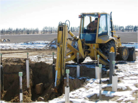
Site Preparation
We used a P & H foundation on this project, which has sixteen 2’ diameter concrete caissons, 30’ deep with threaded anchor bolts running the full depth. The backhoe is preparing the area around the concrete caissons for the top foundation which will be 7’ thick and 24’ in diameter tied together by the anchor bolts shown in the picture.
-
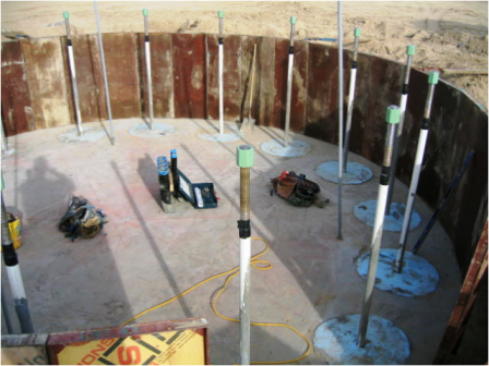
Site prepared for the top foundation
The site has been prepared with the electrical conduit, grounding rods, floor compacted and leveled and the concrete forms ready to set the base tower section anchor bolts and rebar.
-
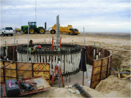
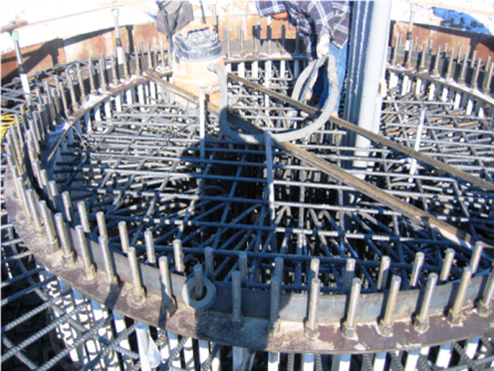
Setting the base tower section anchor bolts
We’re looking at the tower anchor bolts set in a template ring at the top and bottom to keep the anchor bolts perfectly aligned as the tolerances are extremely tight. There are 160 anchor bolts, each encased in a poly tube to allow for expansion and contraction in the concrete.
-
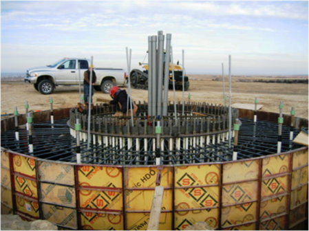
Almost ready to pour concrete
Making the final check and finishing the rebar ties in preparation to pour the top foundation. The surface of the foundation will be slightly above ground level for proper water drainage.
-
Another view prior to the concrete pour
-

Concrete had to be pumped in to eliminate voids
-
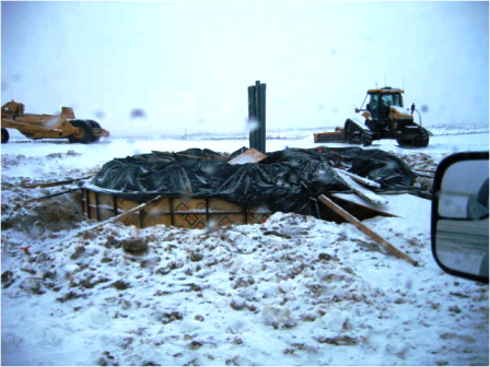
It’s COLD in Wray, Colorado USA!
The concrete has been covered with blankets and plastic during the curing period. This process took about 30 days.
-

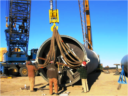
Unloading the first tower section on site
The “Tailing” crane and a second small crane are used to unload the first tower section as it is delivered to the project site.
-

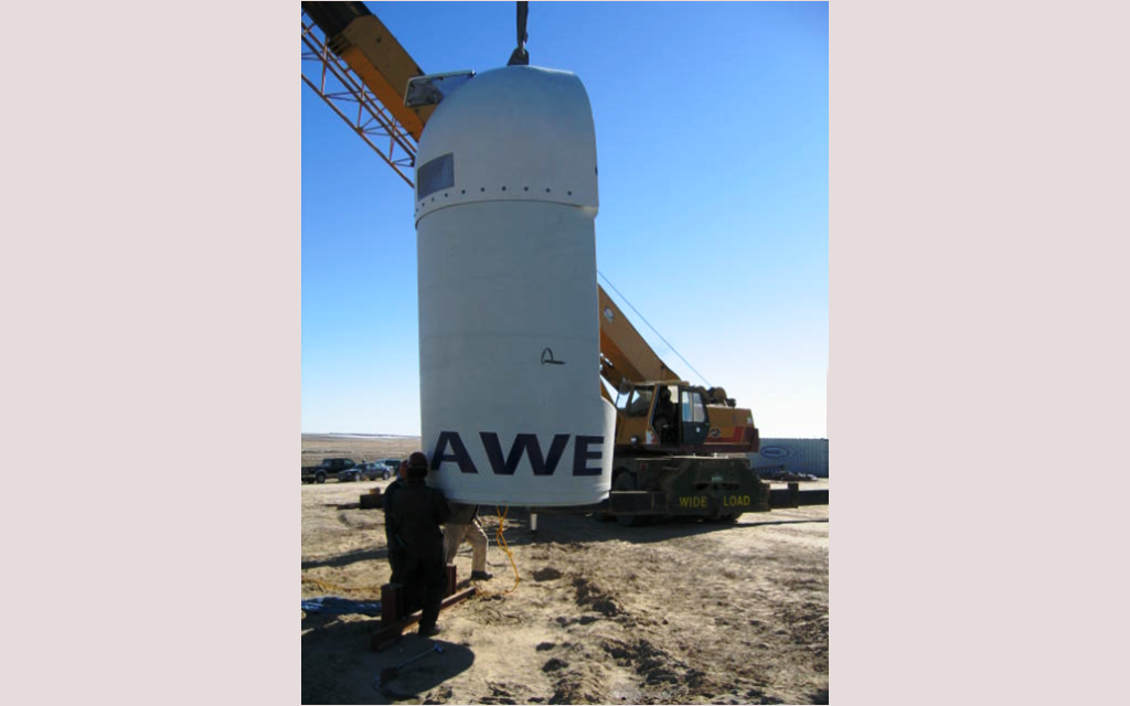
Taking delivery of the Wind Generator
This is an AWE 900 KW Wind Generator being delivered to the site. Somewhat different in size and configuration than other wind turbines going up in the area.
-
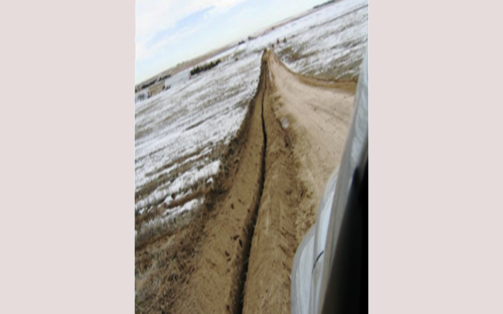
Trench for the underground electrical wires
On this project we buried approximately 1.5 miles of electrical cables to reach our point of interconnect to the existing power grid. The cables were buried 4 feet deep.
-
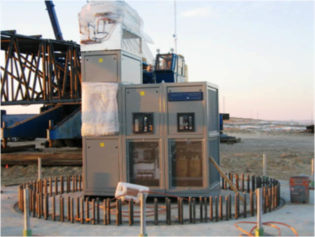
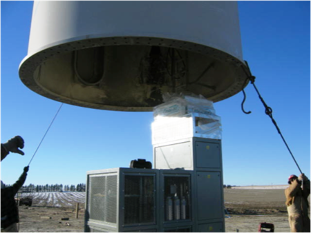
Down tower assembly set in place ahead of tower
We set the electronic equipment (down tower assembly) on the foundation prior to setting the base tower section as it would not easily to through the door in the base tower section.
-
Ready to lift the base tower section
-
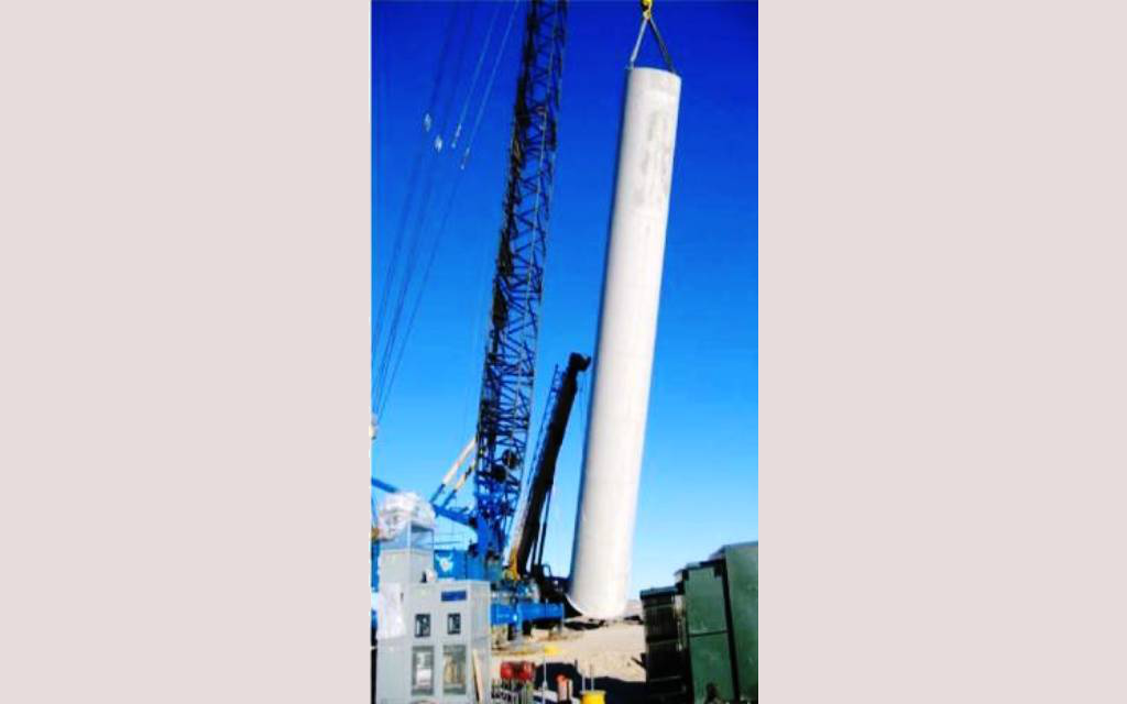
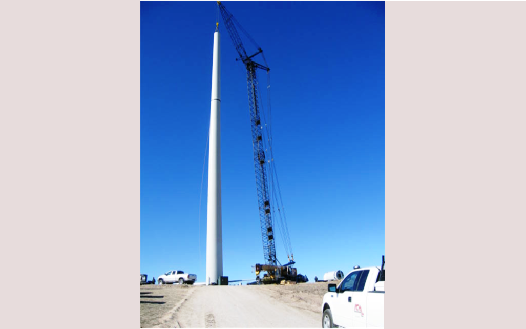
Lifting the base tower section
This view is showing the base tower section being lifted and will be set down over the “down tower assembly” onto the foundation. You can also see the pad mount transformer setting off to the side of the foundation.
-
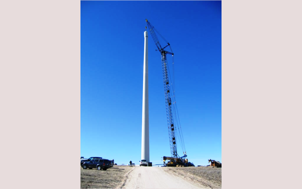
Setting the base tower section
-

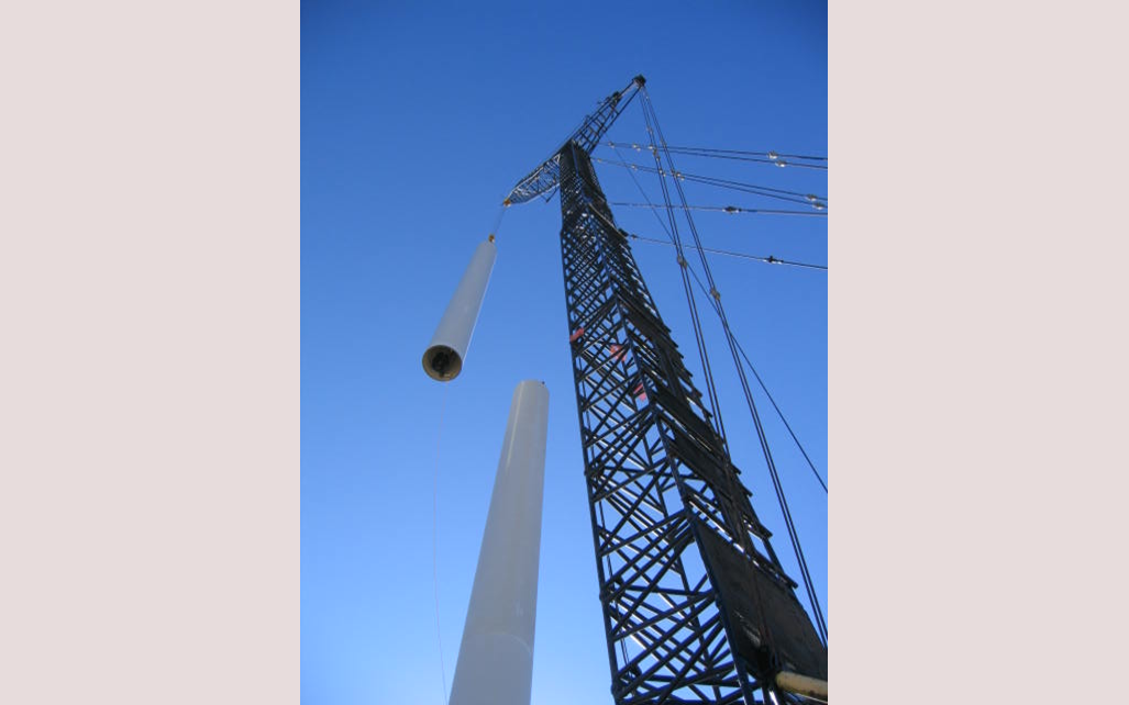
Lifting the middle tower section into place
-
Lifting the top tower section into place
-
Aligning the flange bolts to attach the top section
-
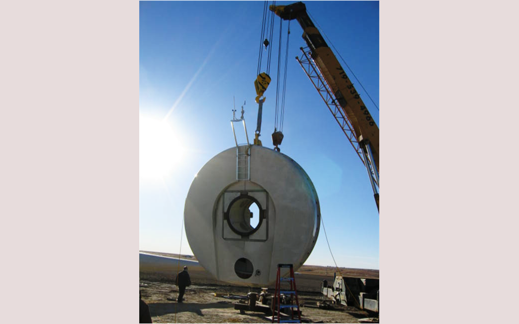
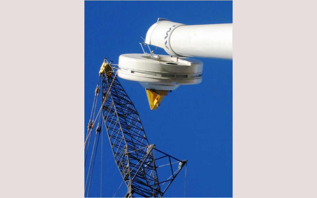
Lifting the nacelle
-
Setting the nacelle into place
-
Lifting the wind generator
-
Aligning the generator to be secured to the nacelle
-
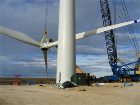
Lifting the hub and blades
The hub and blades were assembled on the ground. Then the hub and blade assembly are lifted into place as one unit to be attached to the generator.
-
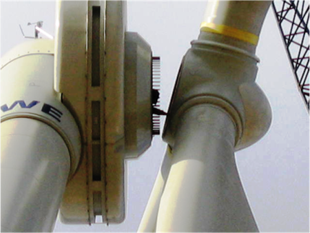
Hub being aligned to the generator
You can see a man working from the inside of the generator to align the hub. As you can imagine, this required a time when there was almost no wind blowing at all.
-
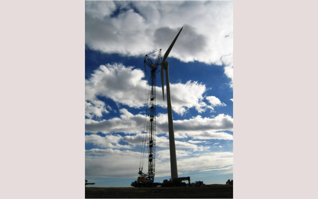
Distant view of mounting the blade assembly
