-
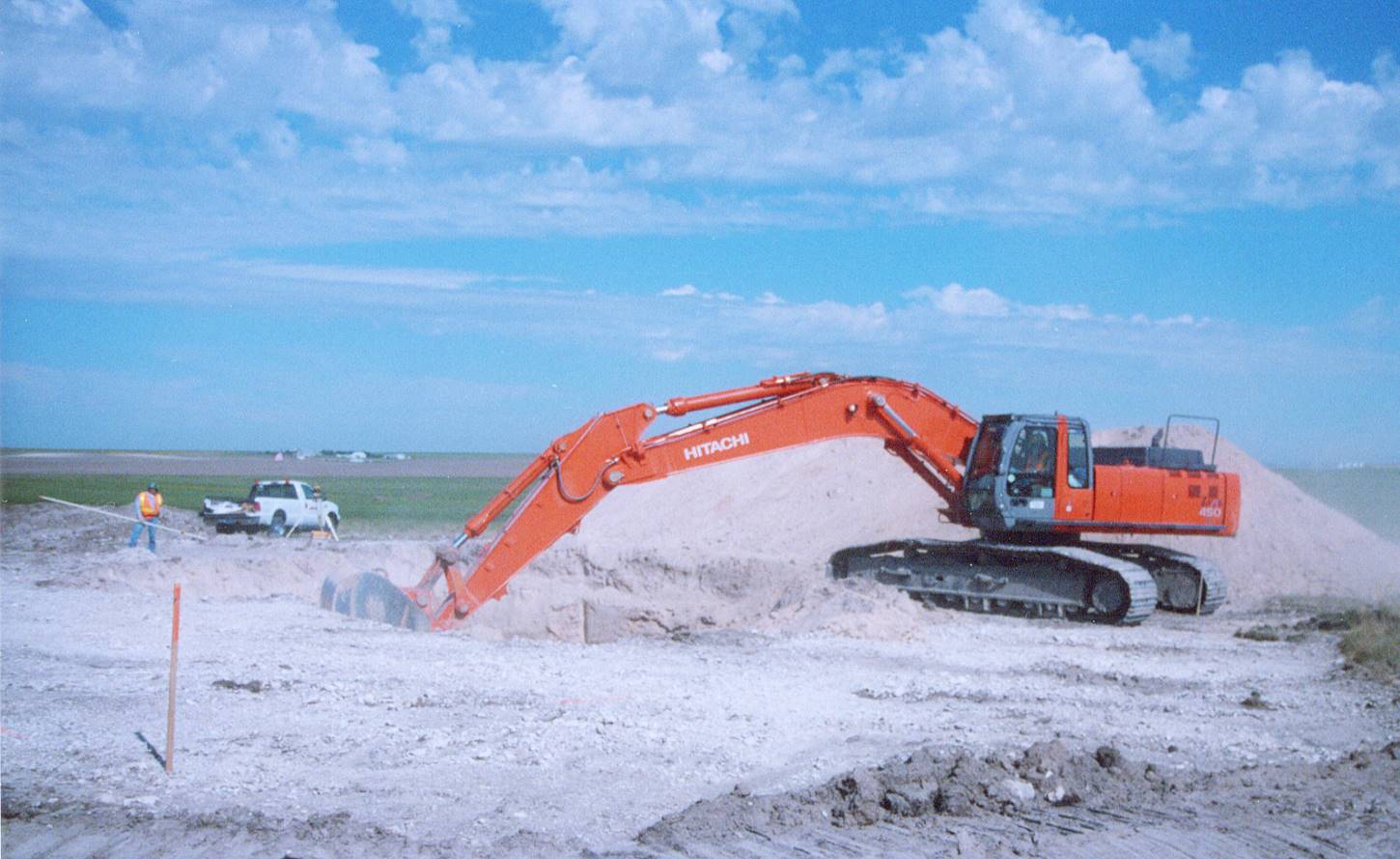
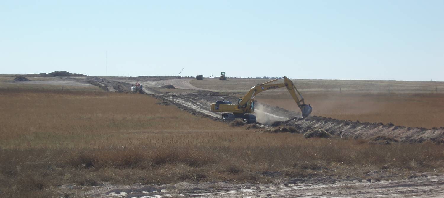
Initial excavation of the turbine foundation
-

52” wide excavating bucket – 3 yard capacity
-
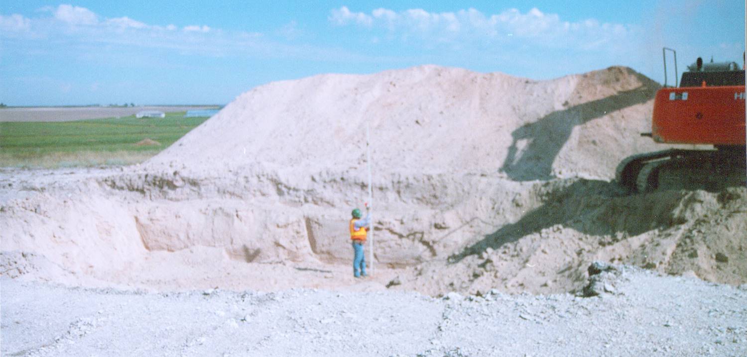
Foundation excavation
65 – 70 ft diameter hex, 9 - 10 ft deep
-
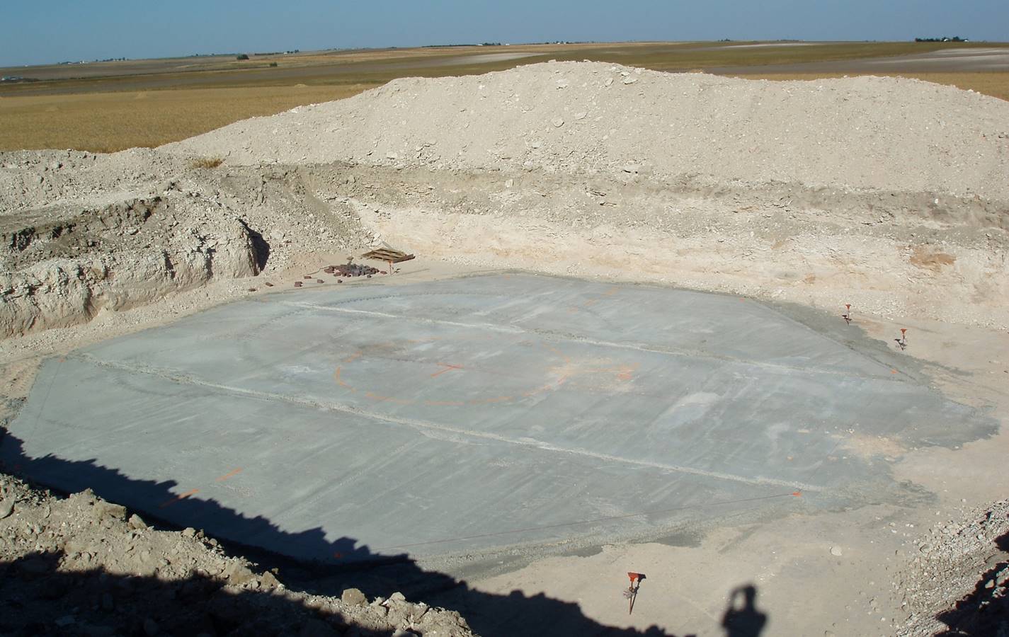
3 - 4” concrete floor base (rat slab) for rebar
-
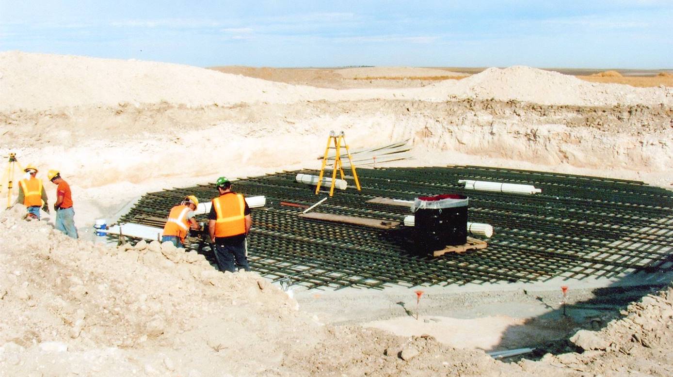
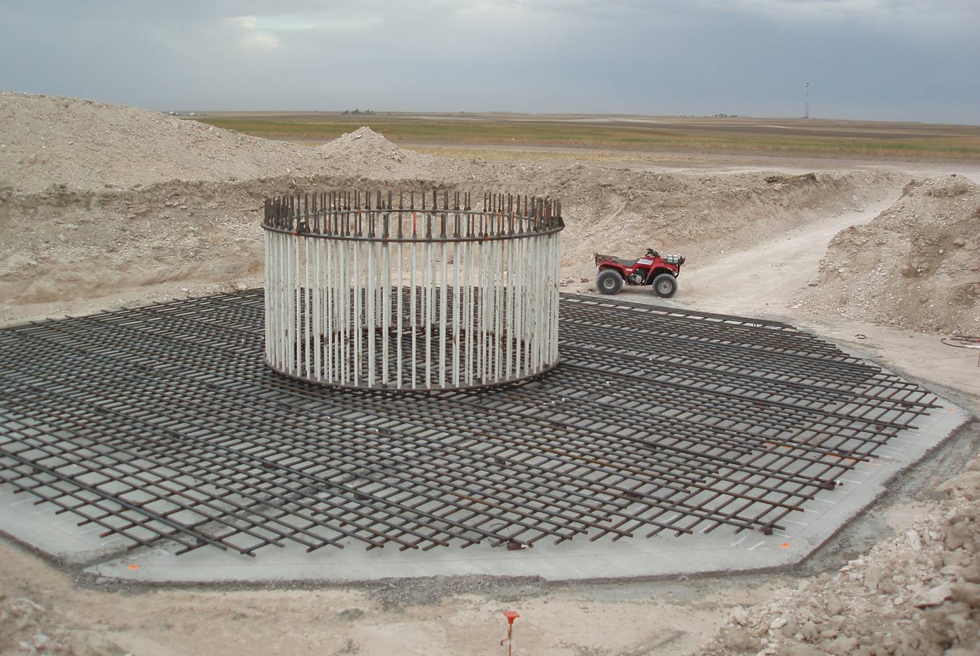
Setting up the rebar structure
-
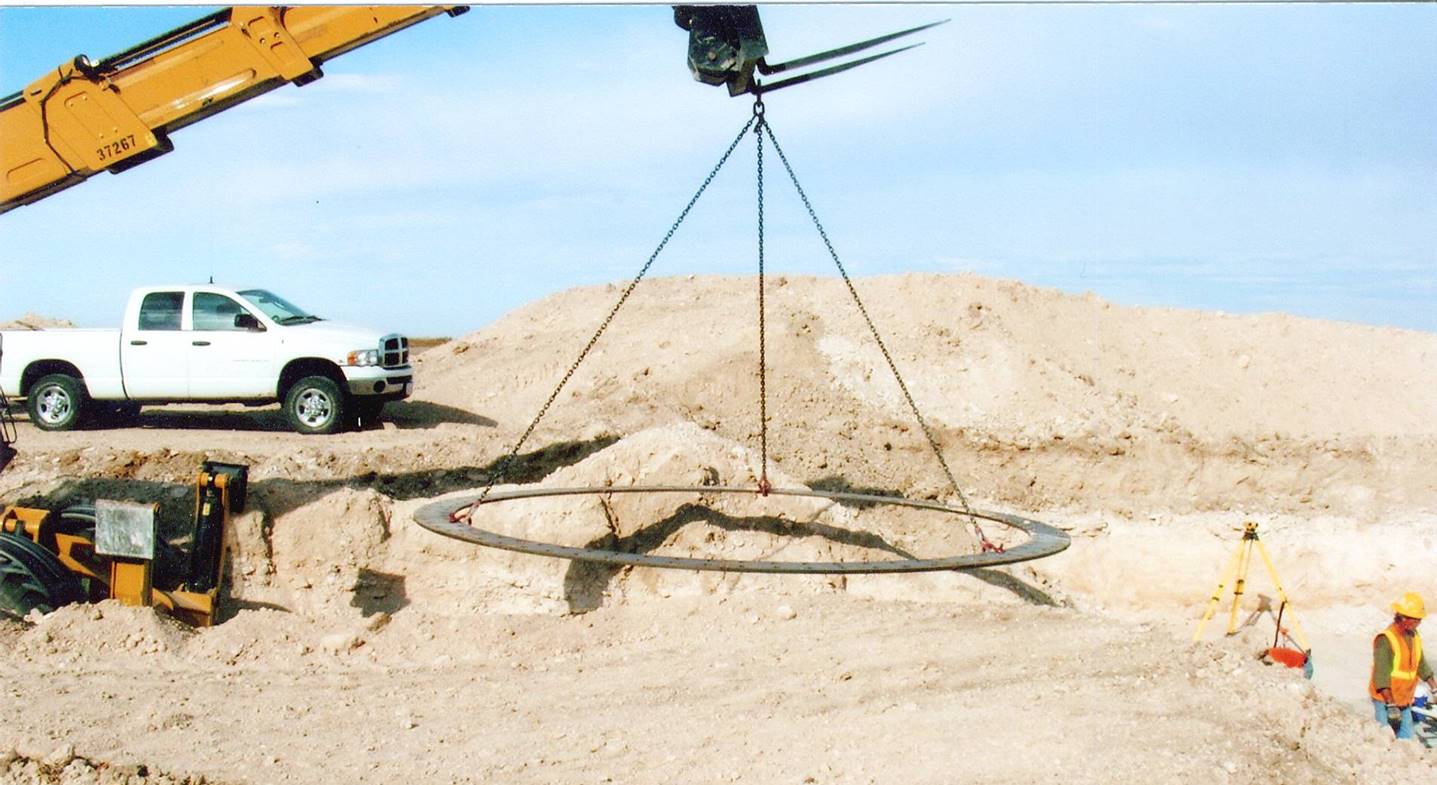
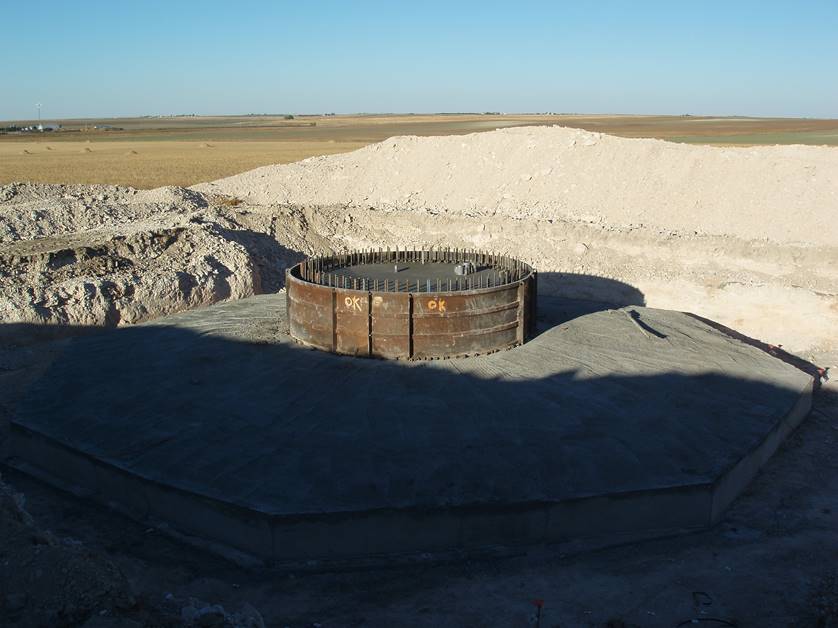
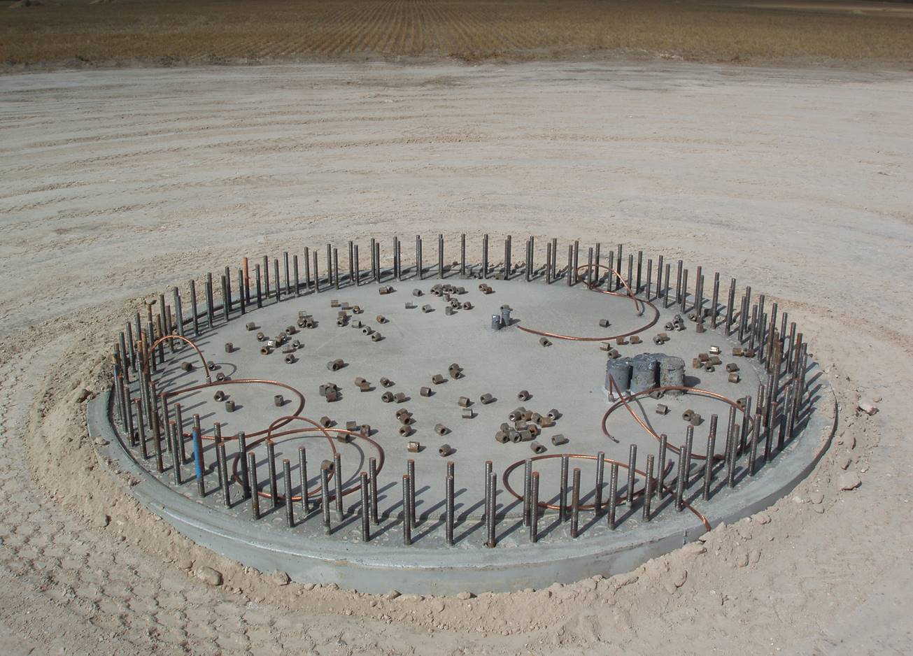
Bolt pattern ring
15 ft. bolt pattern ring form to be centered on the foundation base
-
Bolt ring guide
-
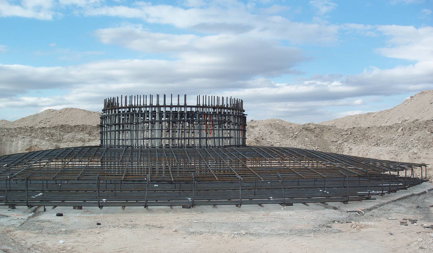
Rebar foundation curved to center ring
-
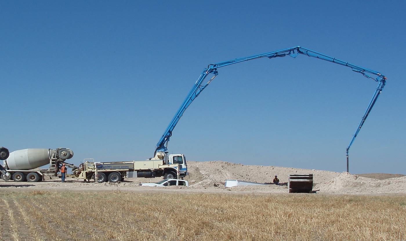
Concrete delivery
Pumper truck pumps 23 loads ( 240 yards ) of concrete into rebar form
-
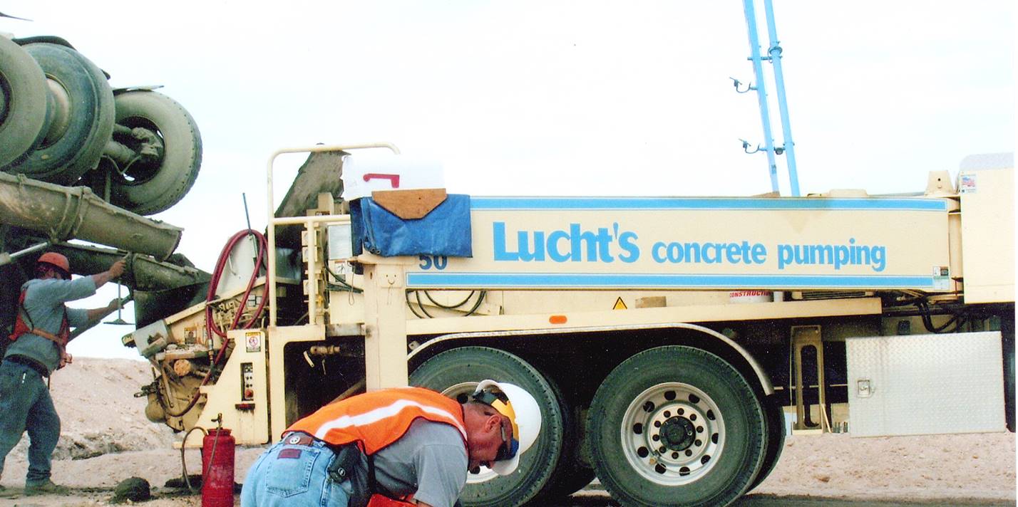
Concrete delivery
Each concrete truck driver inserts his load ticket in the mail box on top of the pumper to indicate the completion of their load
-
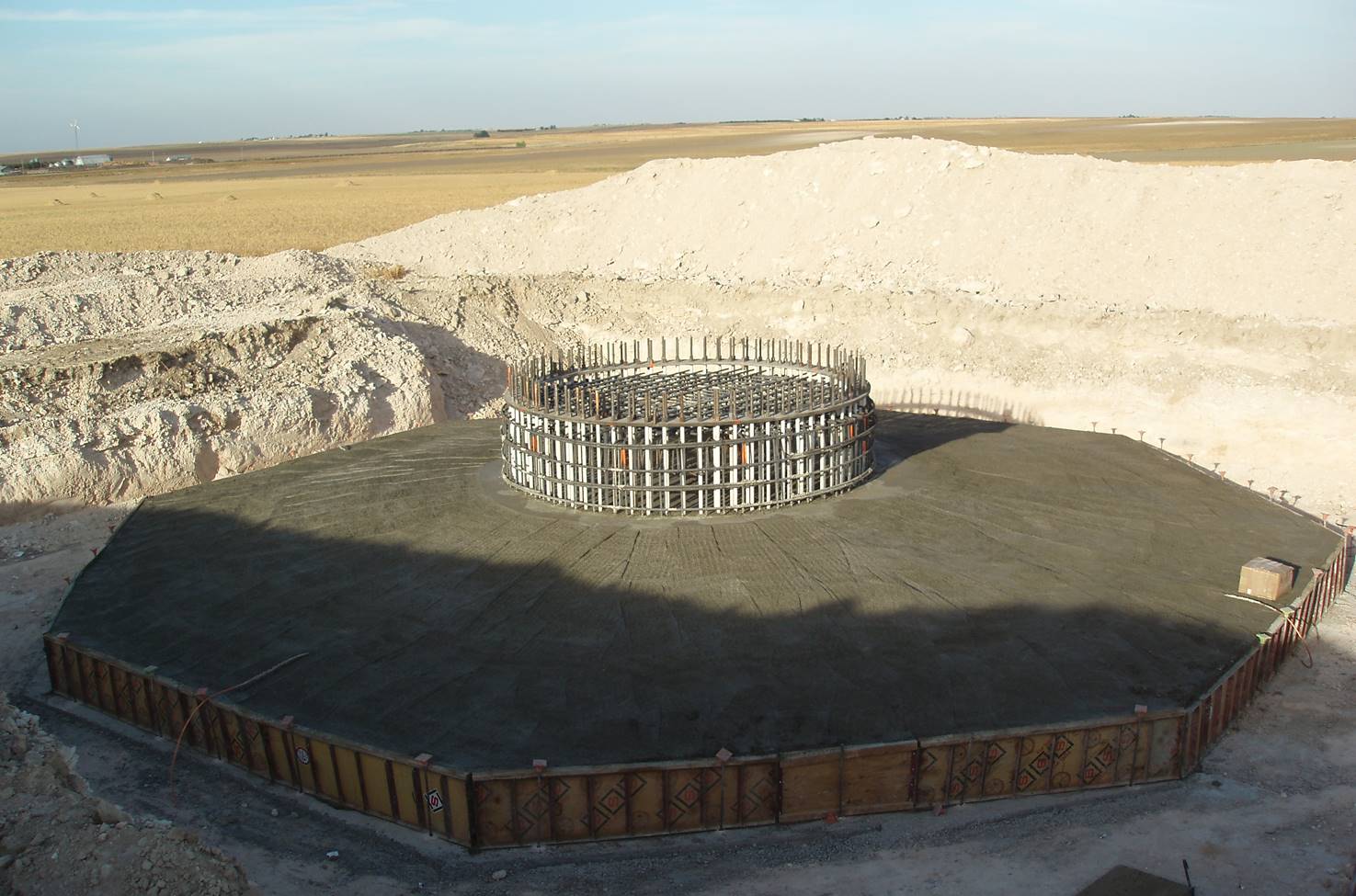
Base platform is filled with concrete
-
Center support
Top center base form over platform base
-
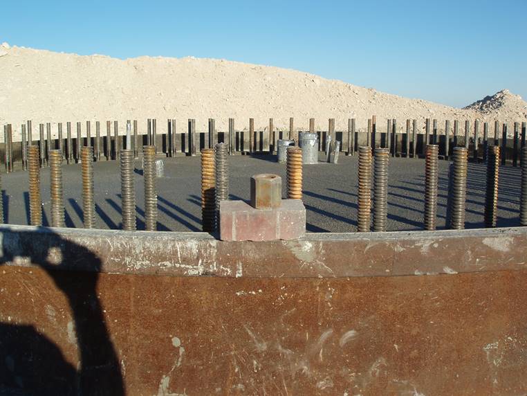
Center support
Note the size of the nut compared to the brick
-
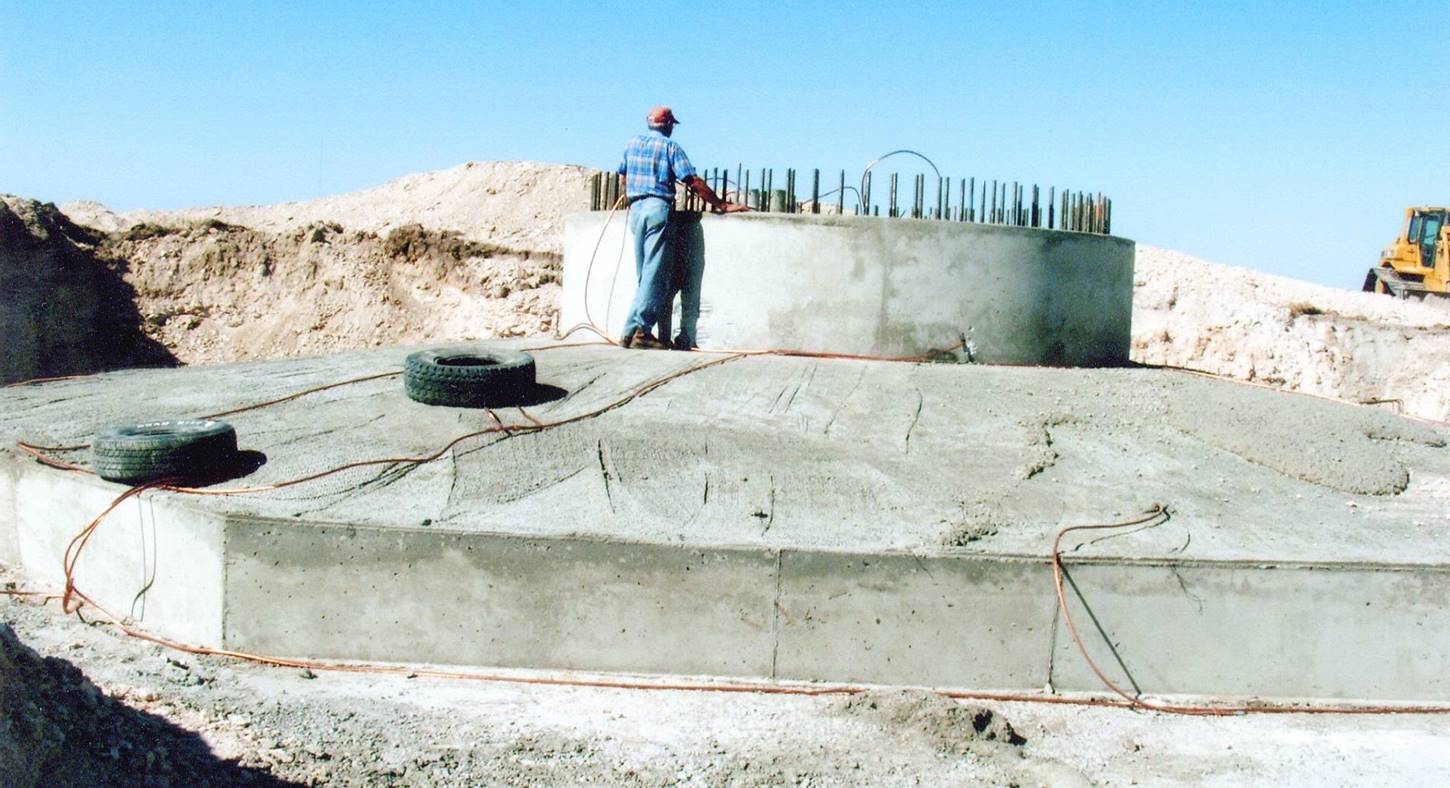
Final foundation completed
-
Final preparation of center support
Dirt filler packed over foundation base up against center support
-
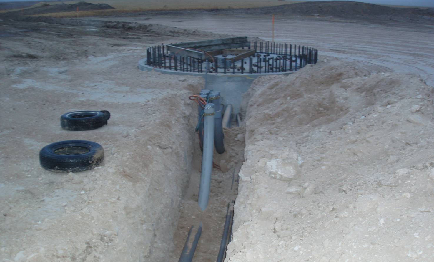
Electrcal conduit
Burying electrical conduit from foundation to future electrical box (transformer)
-
Electrical trench
Electrical trench extends from tower to tower to the sub-station
-
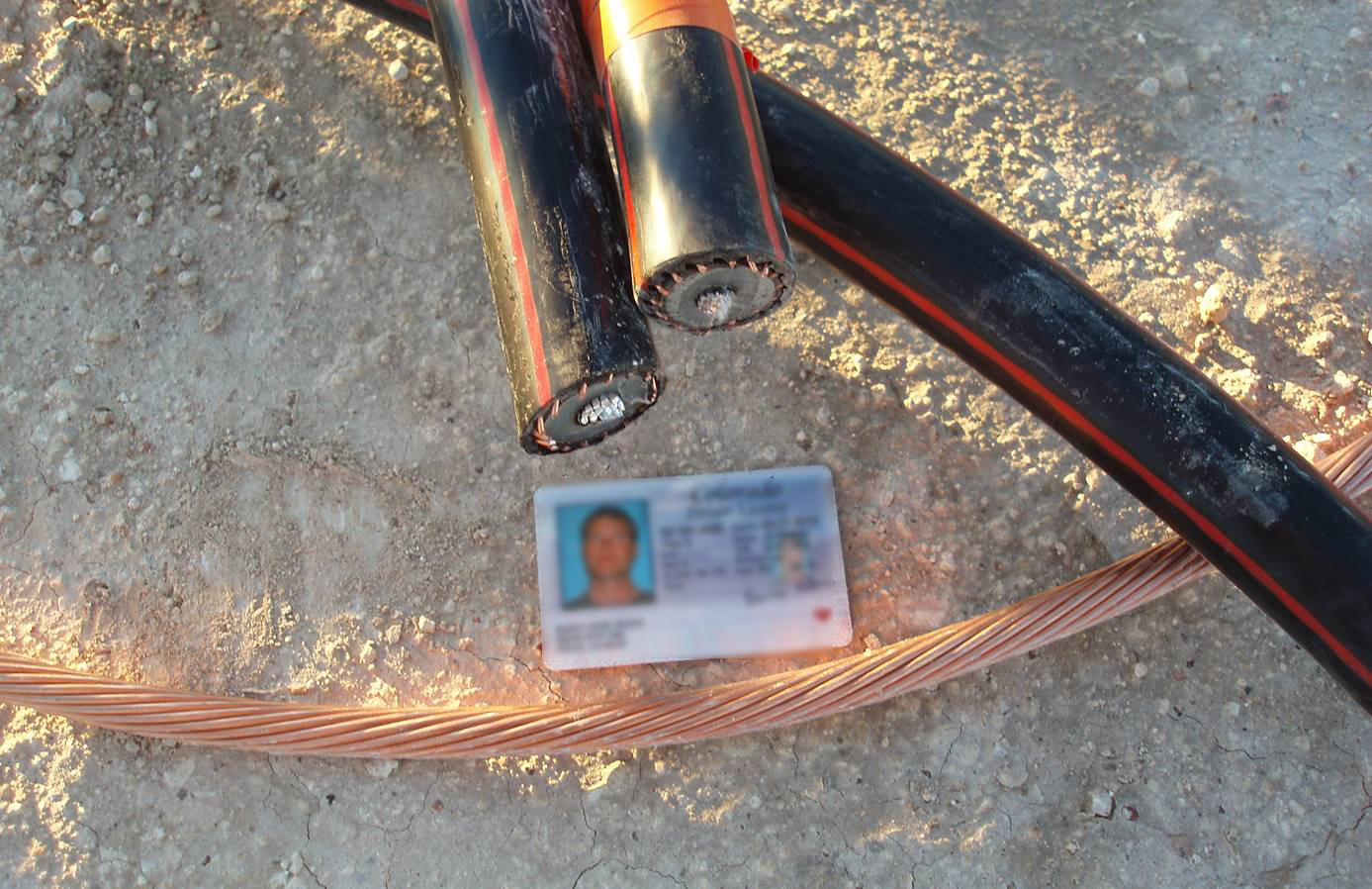
Wiring
Top – insulated electrical wire. Bottom - copper ground wire
-
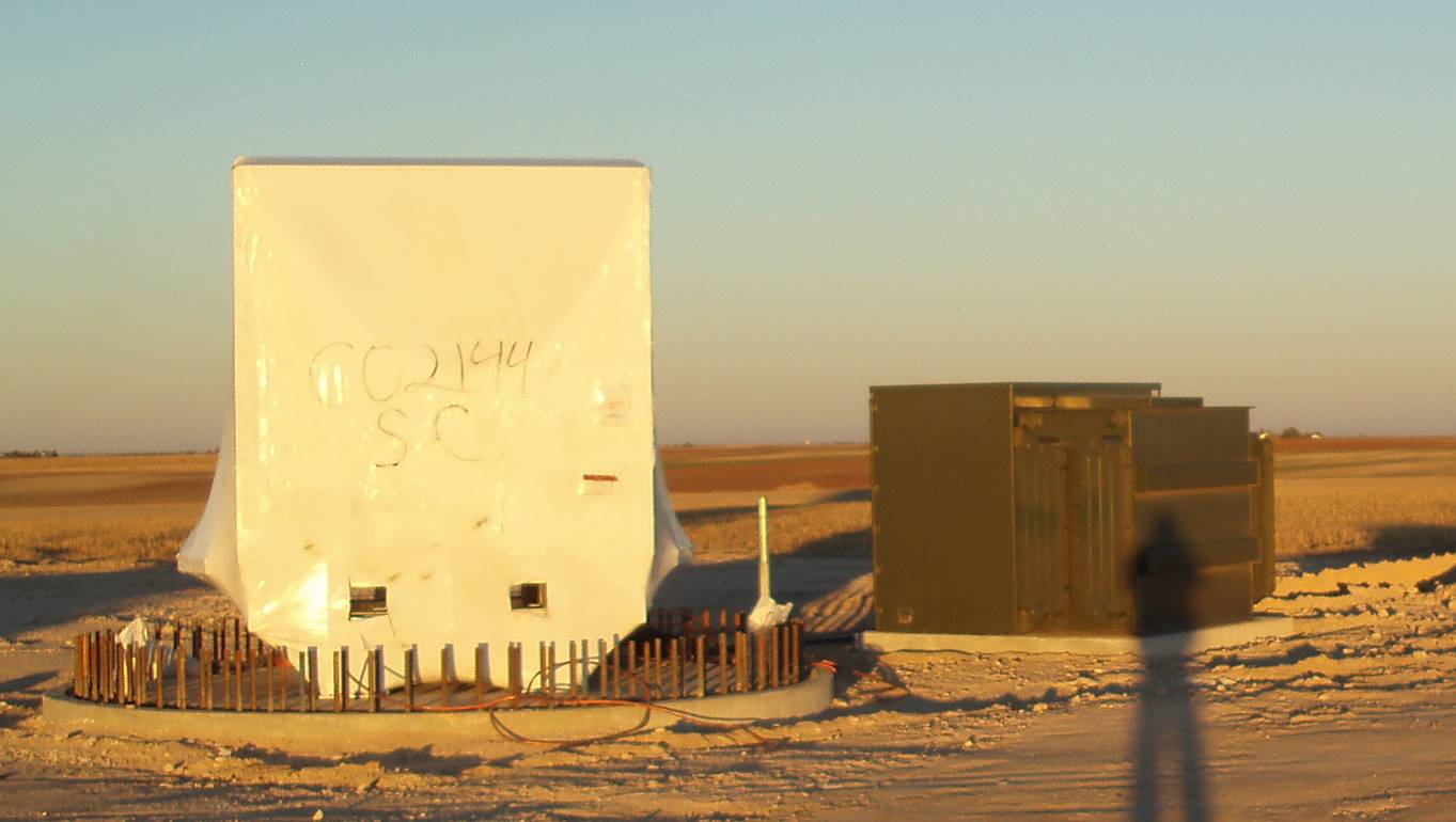
Computer control center and electrical transformer
White shrink wrap covers computer control center that is placed over the tower base, green electrical transformer is set beside tower base
-
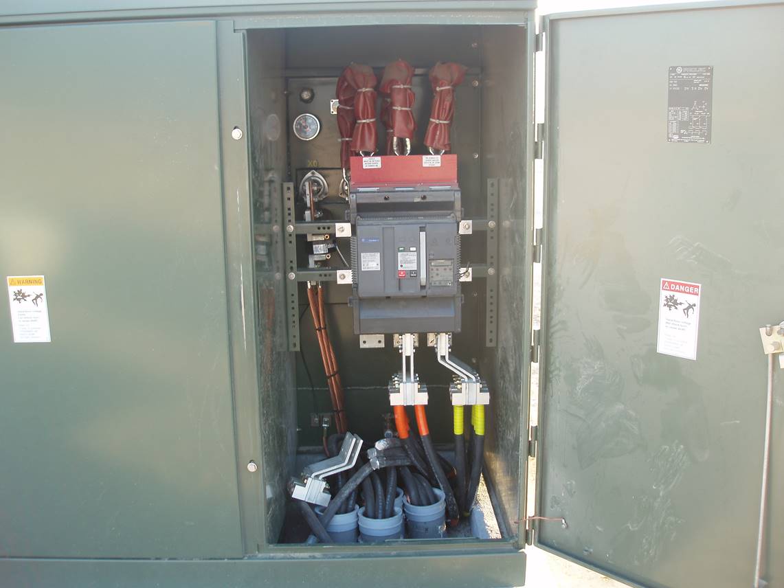
Inside the electrical transformer
-
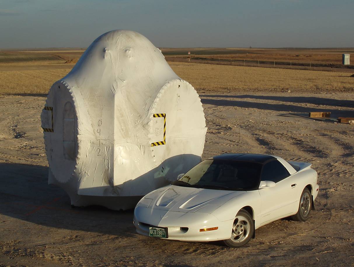
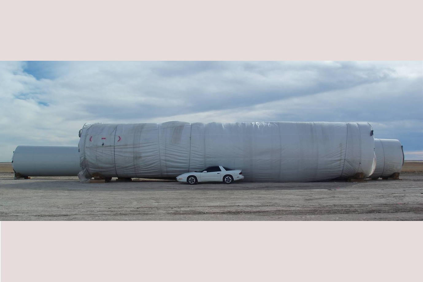
Nose cone shipped in shrink wrap for protection
-

Inside the nose cone
Three total motors for changing the pitch of the blades
-
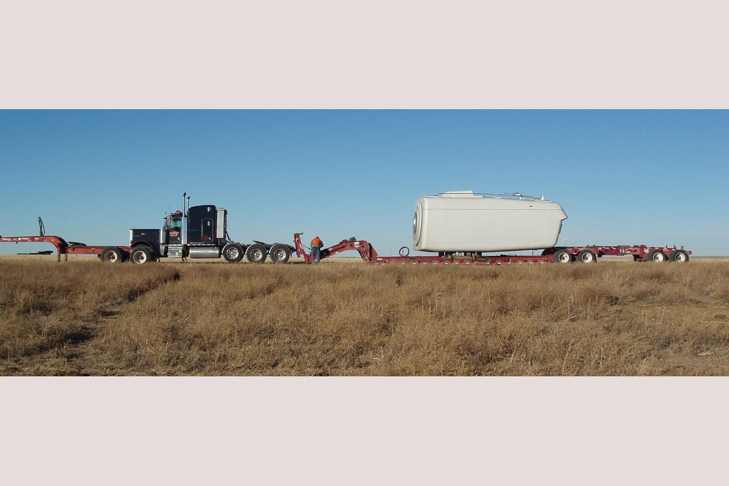
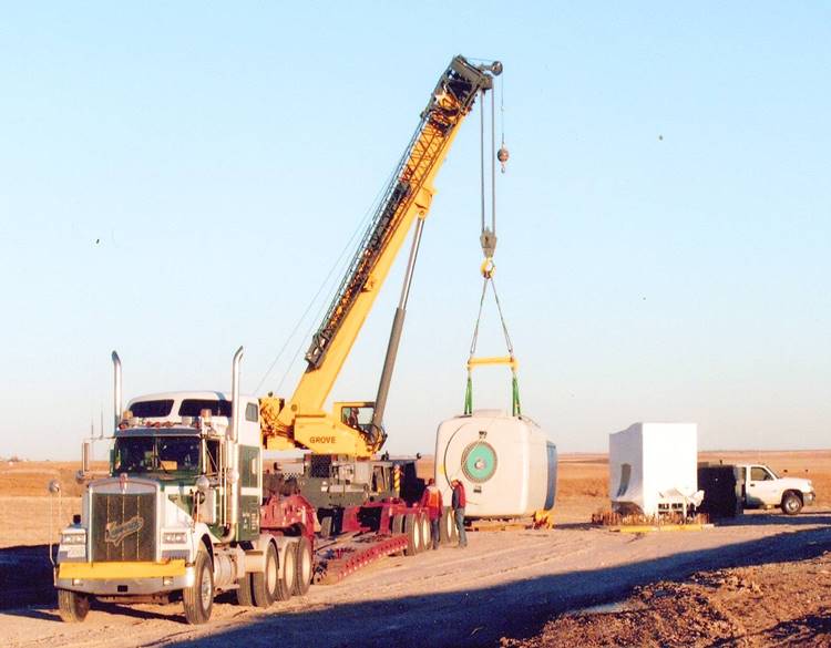
Nacelle arrives on 9 axle trailer
-
Nacelle
Located on top of the tower and houses the main components such as the gear box, generator, main bearing and shaft
-

Nacelle
Size - 29 ft x 11.5 ft x 12.5 ft. Weight - 114,640 lbs (57.32 tons)
-
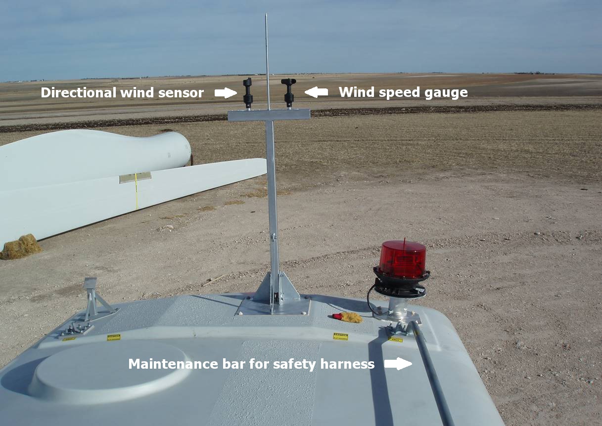
Top of nacelle
-

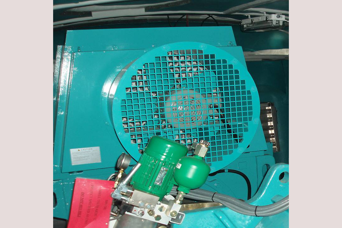
Inside nacelle – generator and gear box
-
Variable speed, doubly-fed induction generator
Maximum power output - 1.5 MW or 1,500 kW. Dimensions – 11 ft x 5.5 ft x 6 ft. Weight – 17,636 lbs
-
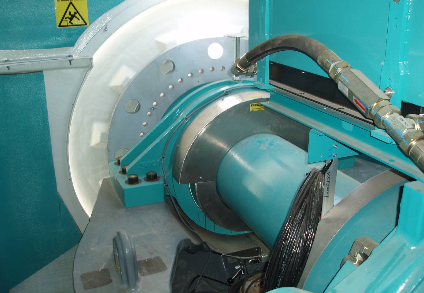
Main power shaft – approximately 23” diameter
-
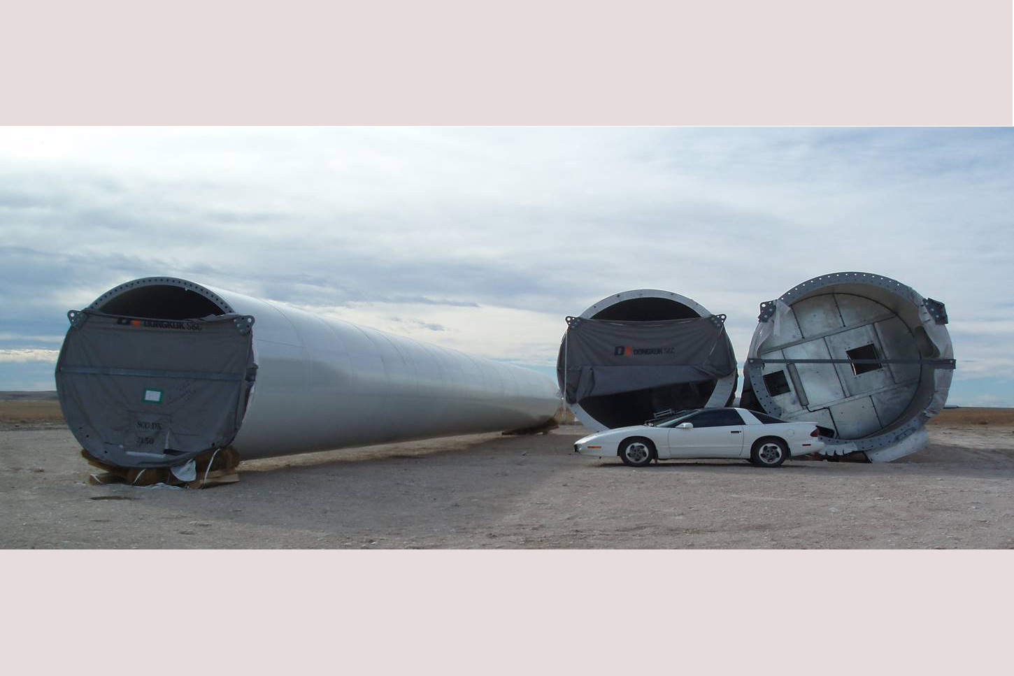
Three tower sections
Base diameter = 14.92 feet
-
Three tower sections
Bottom section – 73 ft long, weighs 64 tons. Mid section - 82 ft long, weighs 42 tons. Top section - 98 ft long, weighs 33 tons
-
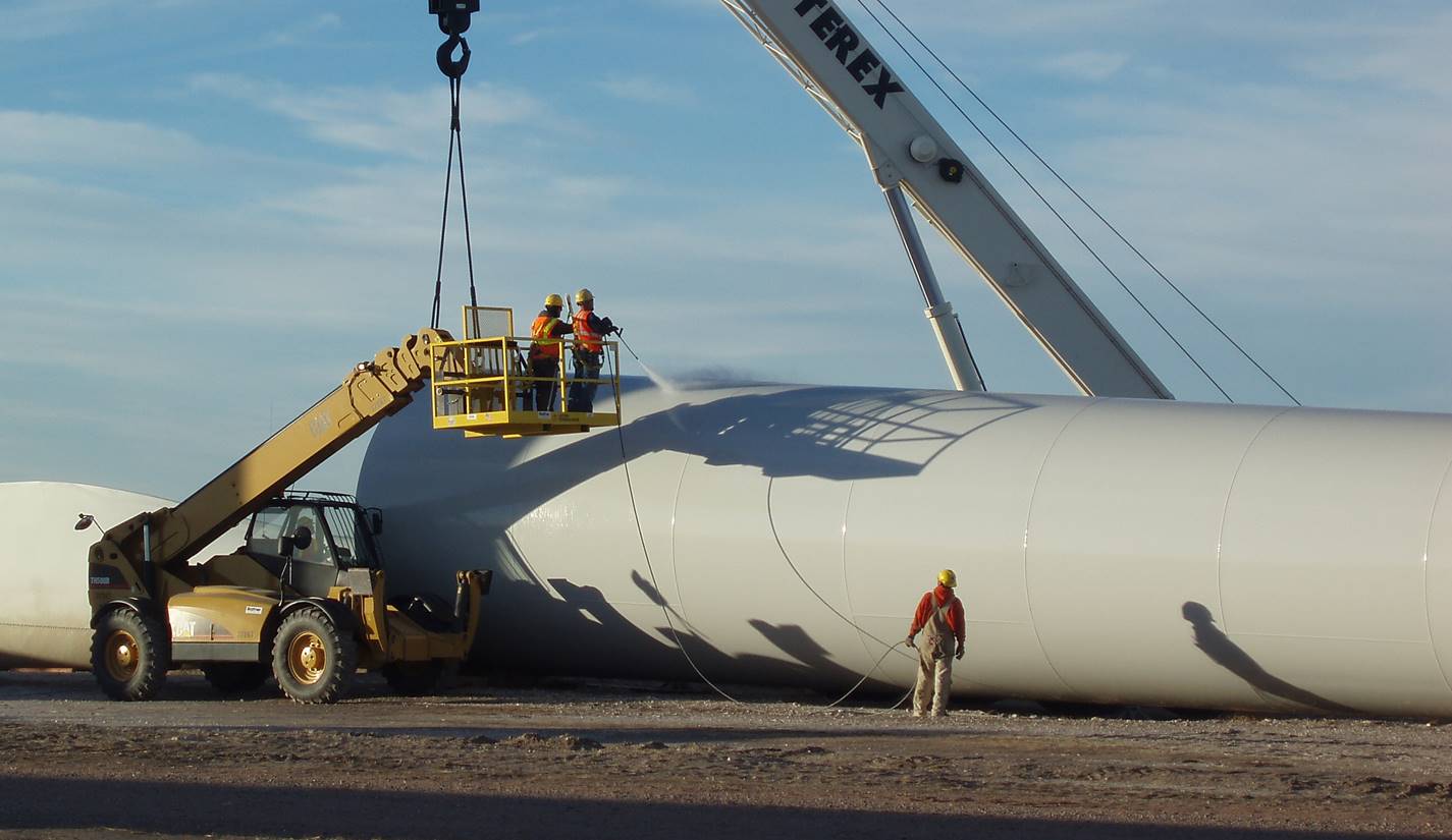
Cleaning tower components
All tower components are thoroughly washed inside and out before assembly
-
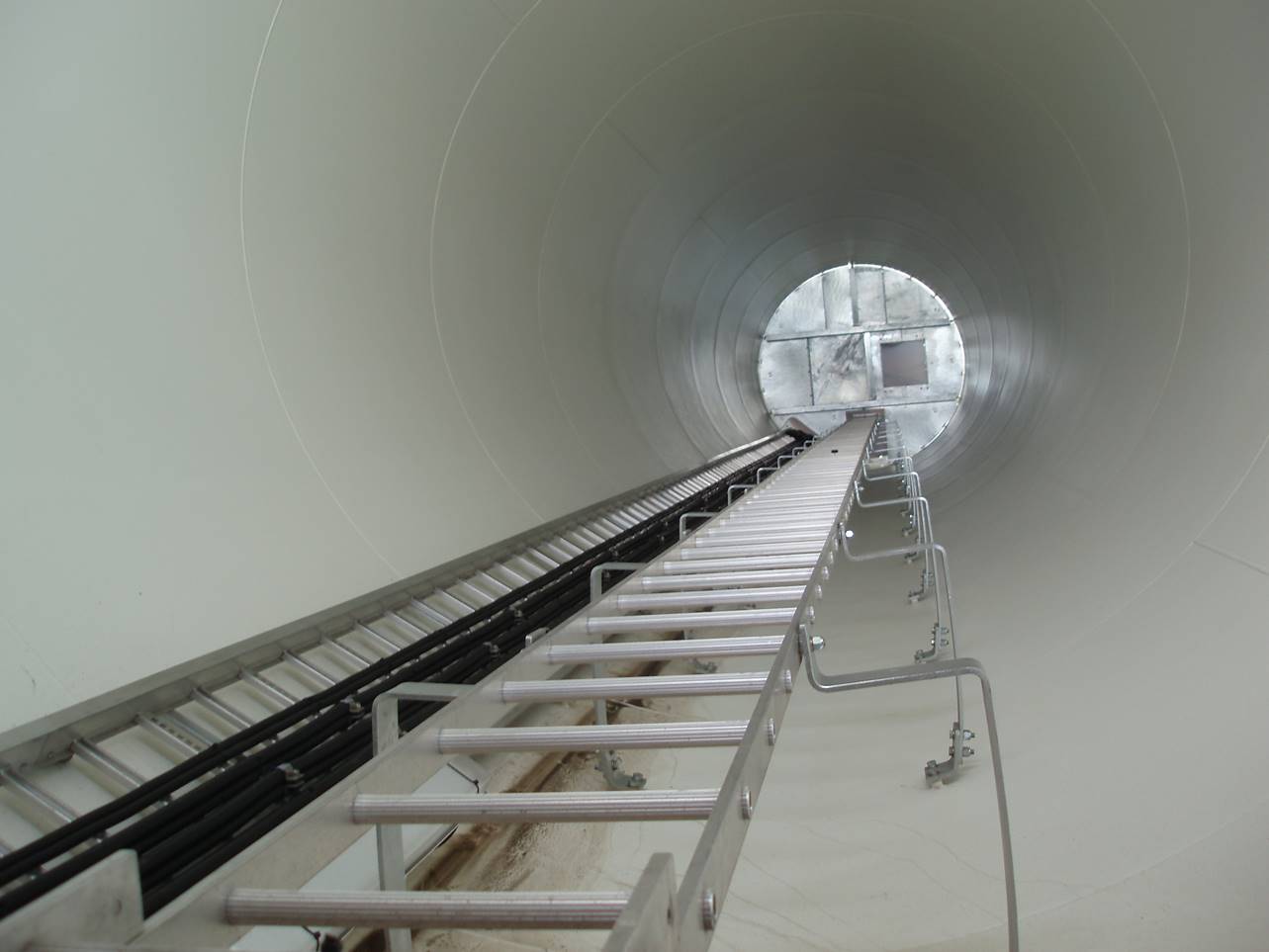
Ladder inside the tower base
-

Red (mid-size) crane positions bottom two tower sections
-

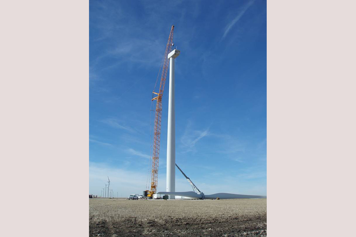
Final tower section is lifted into position
-

Final tower section fastened into position
-

Nacelle lifted to position on top of tower
-
Nacelle fastened to top of tower
-

Arrival of the blades
122 ft. long blades arrive on site. Each blade weighs approximately 13,000 pounds
-

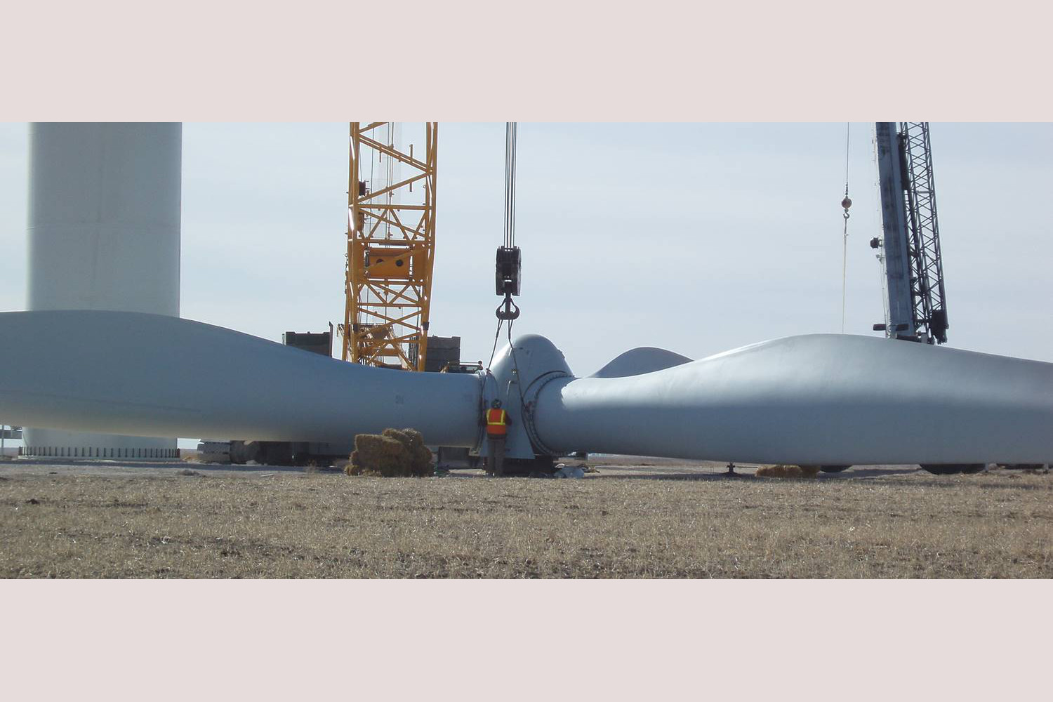
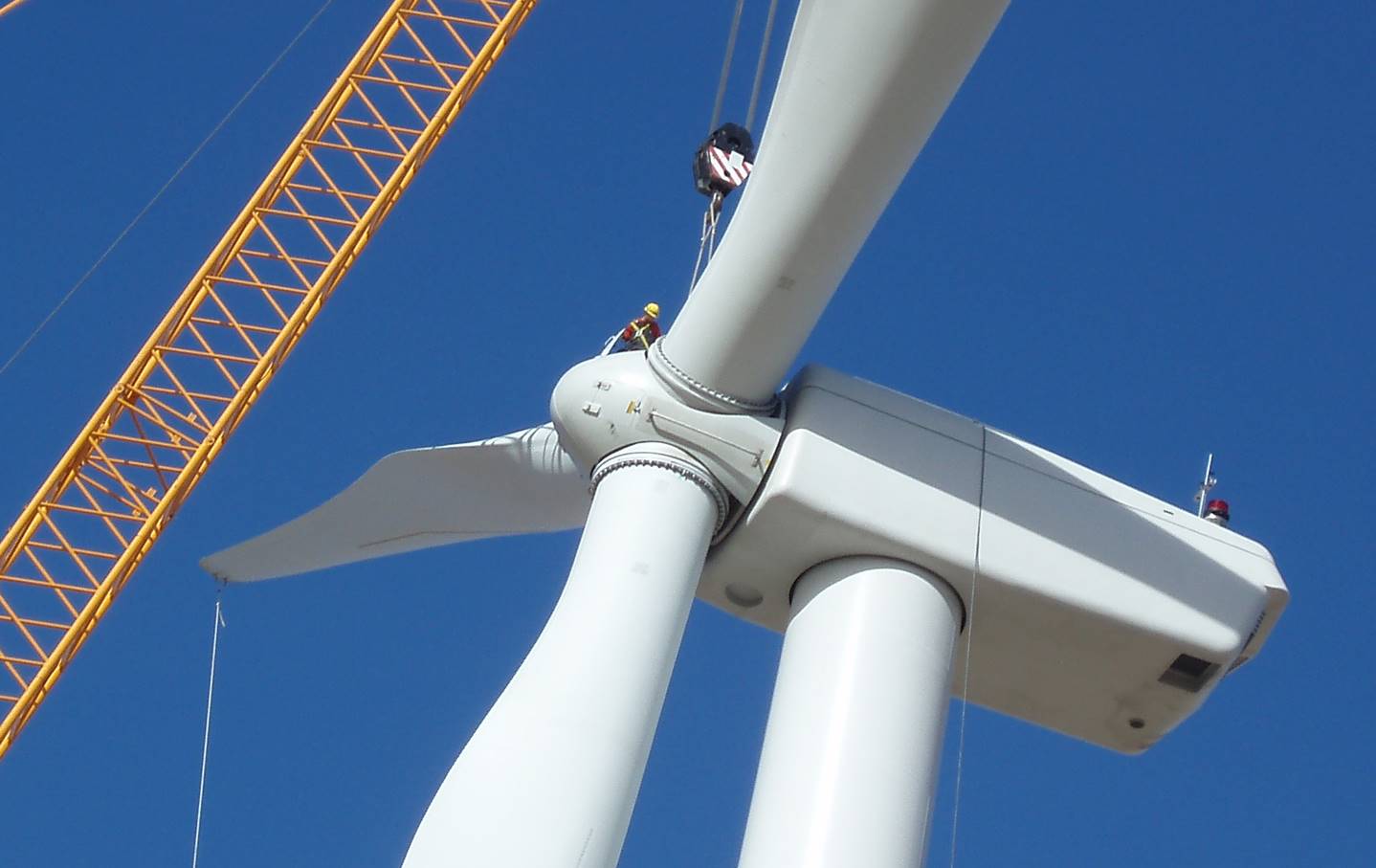
Blades are bolted to the hub
Rotor is composed of three blades and a hub. Diameter - 252 feet. Overall weight - 73,193 pounds (36.6 tons)
-

Blades are bolted to the hub
After blades are bolted to hub, marks are made to easily identify any movement
-
Lifting the rotor assembly and blades
Rotor being wrapped into crane cradle hook (note man in orange safety vest)
-
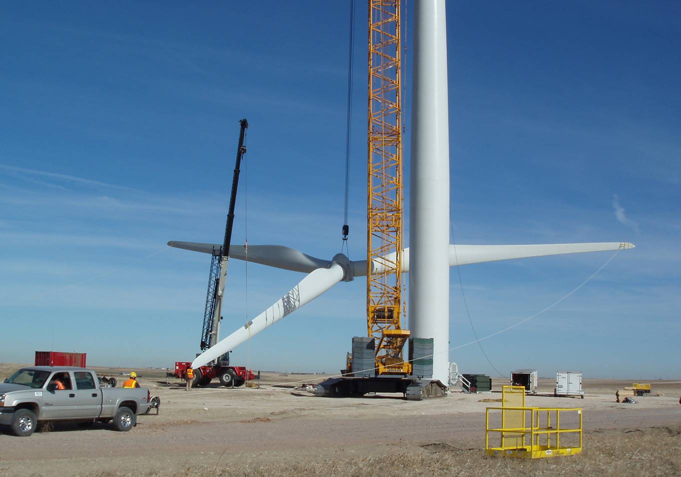
Lifting the rotor assembly and blades
Large crane to lift rotor assembly & small crane supports bottom blade from dragging
-

The blades go up!
-
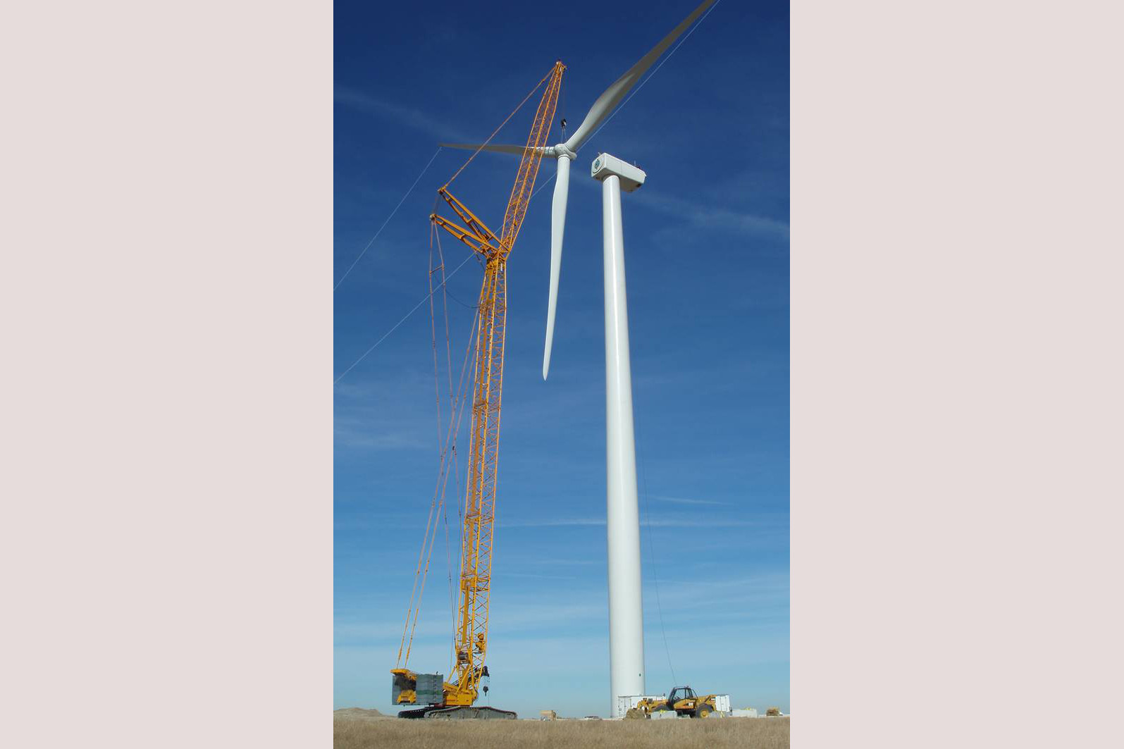
The blades go up!
-
Finishing touches
Technician crawls up tower, through the nacelle, and into the hub to bolt rotor to nacelle
-
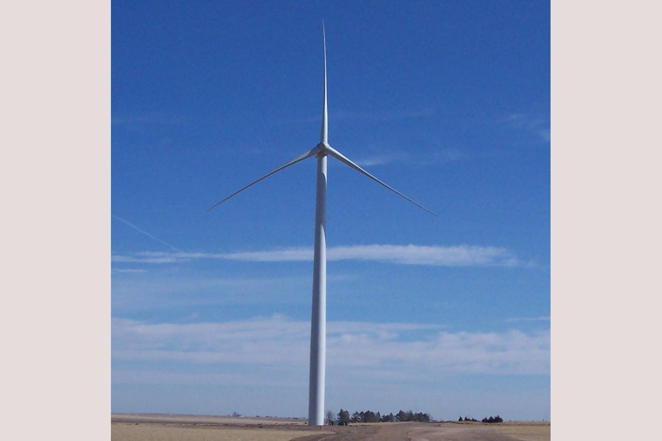
Ready for service!
Tower height - 263 feet. Total height of tower & blade in vertical position - 389 feet. Complete weight of tower, nacelle and rotor - 232 tons
-

View 21st Century technology… providing electricity for our future!
